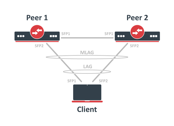
Below are the configuration commands to create a regular LACP aggregation link in RouterOS for the client device:
/interface bonding

add mode=802.3ad name=bond1 slaves=sfp-sfpplus1,sfp-sfpplus2
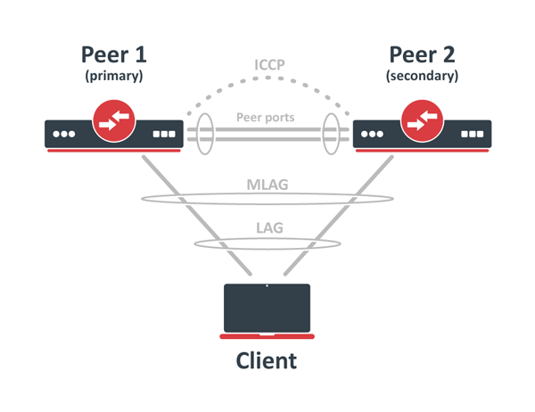
Next, configure the binding interfaces for MLAG on Peer1 and Peer2 devices, using the matching mlag-id configuration on both peer devices:
pear1
/interface bonding

add mlag-id=10 mode=802.3ad name=client-bond slaves=sfp-sfpplus2
pear2
/interface bonding

add mlag-id=10 mode=802.3ad name=client-bond slaves=sfp-sfpplus2
Configure the bridge with VLAN filtering enabled and add the necessary interfaces as bridge ports.
A dedicated untagged VLAN must be applied for inter-chassis communication on a peer port, therefore a different pvid configuration is used.
Below are the configuration commands for Peer1 and Peer2 devices:
pear1
/interface bridge

add name=bridge1 vlan-filtering=yes

/interface bridge port

add bridge=bridge1 interface=sfp-sfpplus1 pvid=99

add bridge=bridge1 interface=client-bond
pear2
/interface bridge

add name=bridge1 vlan-filtering=yes

/interface bridge port

add bridge=bridge1 interface=sfp-sfpplus1 pvid=99

add bridge=bridge1 interface=client-bond
The MLAG requires that the STP, RSTP or MSTP protocol be enabled. Use the same STP priority and STP configuration on connected bridge ports on both nodes.
In this example, the client-bond interfaces use the default untagged VLAN 1 (the default pvid value is 1).
To send these packets through the equipment ports, it is necessary to add them as tagged members of VLAN 1.
Be sure to include equipment ports in all VLANs that are used on other ports on the bridge, both untagged and tagged VLANs.
Below are the configuration commands for both peer devices:
pear1
/interface bridge vlan

add bridge=bridge1 tagged=sfp-sfpplus1 vlan-ids=1
pear2
/interface bridge vlan

add bridge=bridge1 tagged=sfp-sfpplus1 vlan-ids=1
All VLANs used for the bridge's slave ports must also be configured as tagged VLANs for the peer port, so that the equipment port is a member of those VLANs and can forward data.
Finally, specify the bridge and equipment port to enable MLAG.
Below are the configuration commands for both peer devices:
pear1
/interface bridge mlag

set bridge=bridge1 peer-port=sfp-sfpplus1
pear2
/interface bridge mlag

set bridge=bridge1 peer-port=sfp-sfpplus1
Also, check the MLAG status on the devices and ensure that the client LACP has both interfaces up.
Below are the configuration commands for both computers and the client devices:
pear1
[admin@Peer1] > /interface/bridge/mlag/monitor

       status: connected

    system-id: 74:4D:28:11:70:6B

   active-role: primary
pear2
[admin@Peer2] > /interface/bridge/mlag/monitor

       status: connected

    system-id: 74:4D:28:11:70:6B

   active-role: secondary
Client
[admin@Client] > /interface bonding monitor bond1

                      Mode: 802.3ad

           active-ports: sfp-sfpplus1,sfp-sfpplus2

         inactive-ports:

       id LACP system speed: 74:4D:28:7B