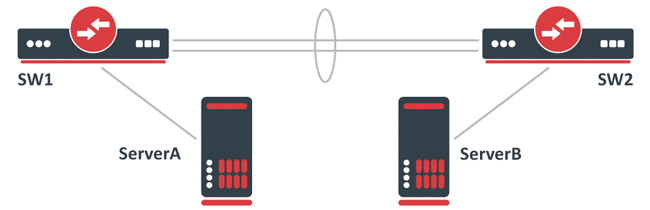
- An 802.3ad bonding mode is added with the name bond1 and the slaves ether1 and ether2.
- A bridge called bridge1 is created.
- The bond1 interface and the sfp-sfpplus1 interface are added to the bridge1 bridge.
Problem
After initial tests, it is observed that the network performance never exceeds the 1Gbps limit, although the CPU load on the servers and network nodes (switches) is low. This is because LACP (802.3ad) uses a broadcast hash policy to determine whether traffic can be balanced over multiple members of the LAG.
In this case, a LAG interface does not create a 2Gbps interface, but rather an interface that can balance traffic over multiple slave interfaces when possible.
For each packet a transmission hash is generated, which determines which member of the LAG the packet will be sent through, thus preventing packets from getting out of order.
There is the option to select the transmission hash policy, which typically allows you to choose between Layer 2 (MAC), Layer 3 (IP), and Layer 4 (Port).
On RouterOS, this can be selected using the transmit-hash-policy parameter. In this case, the transmission hash is the same since packets are sent to the same MAC address as well as the same IP address and Iperf also uses the same port, thus generating the same transmission hash for all packets and preventing load balancing between LAG members.
It should be noted that packets will not always be balanced over LAG members even when the destination is different, since the standardized transmission hash policy may generate the same transmission hash for different destinations.
Symptoms:
- Traffic passing only one member of the LAG.
Solution
Select the appropriate transmission hash policy and properly test network performance.
The easiest way to test such configurations is to use multiple targets. For example, instead of sending data to a single server, data should be sent to multiple servers.
This will generate a different transmission hash for each packet and make load balancing between LAG members possible.
In some cases, you might consider changing the bonding interface mode to increase overall performance.
For UDP traffic, balance-rr mode might be sufficient, but may cause problems for TCP traffic.
You can read more about selecting the right mode for your setup here.
Additional Aspects to Consider:
Bonding Mode Selection
The choice of bonding mode is crucial. While balance-rr (round-robin) may be effective for UDP traffic, it may not be ideal for TCP due to the possibility of packet reordering. Therefore, it is important to consider the type of traffic that will predominate in the network when choosing the bonding mode.
Influence of Network Configuration
Other aspects of the network configuration can also influence LAG performance. For example, switch configuration, hardware capabilities, and network policies can affect how traffic is handled across LAG interfaces.
Monitoring and Diagnosis
It is essential to implement monitoring and diagnostic tools to better understand how traffic is behaving through the LAG. Tools like Wireshark or even diagnostic features built into switches can provide valuable information.
Performance and Capacity Considerations
Although the LAG interface can theoretically achieve a bandwidth of 2Gbps in this scenario, it must be remembered that the actual performance can be affected by multiple factors, such as the quality of the cabling, the distance between the devices and the hardware configuration itself.
Various Tests
Testing with different configurations and traffic types can help identify the best configuration for a specific environment. This could include varying the destination IP address, port, or even the type of traffic (TCP vs UDP).
Firmware and Software Update
Ensuring that both switches and servers are running the latest, most stable version of their firmware and software can resolve previously unidentified issues and improve overall performance.
Conclusion
Load balancing on a LAG interface is a complex process that requires careful configuration and a detailed understanding of the network and its components.
Through proper transmission hashing policy selection and extensive testing, network performance can be optimized and ensure that available resources are used efficiently.
Additionally, staying abreast of updates and best practices in network configuration can significantly contribute to the effectiveness and stability of your network environment.