Digital modulations are a type of modulation in which digital information is transmitted by modifying one or more parameters of an analog carrier signal. Digital information is represented in the form of binary signals, which are voltage or current pulses that have two possible values: high or low, 1 or 0.
At the end of the article you will find a small test that will allow you assess the knowledge acquired in this reading
Digital modulations are used in a wide variety of applications, such as data transmission via cable, radio, fiber optics and satellite. They are also used in control systems, where it is necessary to transmit digital signals reliably.
Characteristics of digital modulations
Digital modulations have a series of characteristics that distinguish them from analog modulations:
Interference resistance
Digital modulations are more resistant to interference than analog modulations. This is because digital information is represented in the form of pulses, which are easier to detect and recover than analog signals.
Bandwidth efficiency
Digital modulations are more bandwidth efficient than analog modulations. This is because digital information can be transmitted with less power and therefore less bandwidth.
Ease of implementation
Digital modulations are easier to implement than analog modulations. This is because digital information can easily be represented in the form of pulses.
Applications of digital modulations
Digital modulations are used in a wide variety of applications, such as:
Cable data transmission
Digital modulations are used in cable data transmission, such as Ethernet, USB and HDMI.
Radio data transmission
Digital modulations are used in radio data transmission, such as Wi-Fi, Bluetooth and 4G/5G.
Fiber optic data transmission
Digital modulations are used in fiber optic data transmission, such as high-speed Internet.
Lighting Control systems
Digital modulations are used in control systems, where it is necessary to transmit digital signals reliably.
Operation
Digital modulations are techniques that allow digital information (bits) to be transmitted over an analog communication medium. These techniques are essential in digital communication systems, since they allow the efficient and reliable transmission of binary data. Here I explain how digital modulations work in general:
Binary Data Representation
Digital information is represented by a sequence of bits, where each bit can have a value of 0 or 1. This information represents the signal to be transmitted.
Mapping to Symbols
Before modulation, the bits are grouped into symbols. Each symbol represents a specific combination of bits. The number of bits per symbol depends on the modulation scheme used.
Amplitude, Phase or Frequency Modulation
In digital modulation, information is “embedded” in a carrier wave. There are several types of modulation, including:
- Amplitude Modulation (AM): The amplitude of the carrier wave varies depending on the information.
- Phase Modulation (PM or PSK – Phase Shift Keying): Modifies the phase of the carrier wave to represent information.
- Frequency Modulation (FM or FSK – Frequency Shift Keying): It changes the frequency of the carrier wave in response to information.
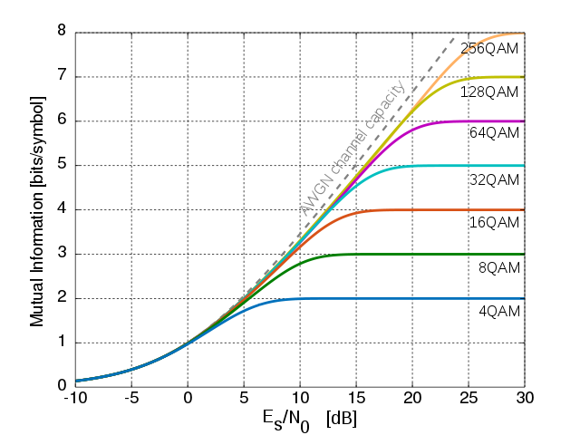
Constellation and Phase Space
In more complex modulation schemes, such as quadrature amplitude modulation (QAM), a phase space or constellation is used to represent multiple bits in a single symbol. In the constellation, each point represents a unique combination of amplitude and phase.
Transmission by the Media
The modulated signal is transmitted through the communication medium, which can be a cable, wireless channel or optical medium.
Reception and Demodulation
At the receiving end, the signal is demodulated to extract the information. Demodulation reverses the modulation process, recovering the symbols and, subsequently, the original bits.
Decoding
The demodulated bits are decoded to recover the original information. This involves converting the symbols back into the original bit sequence.
Error Processing
In digital communication systems, it is common to include techniques to correct or detect errors. This involves adding redundancy bits (error correction codes) that allow information to be recovered even if errors occur during transmission.
These basic steps describe the general operation of digital modulations. The choice of the specific modulation scheme depends on factors such as available bandwidth, transmission channel conditions, and system complexity.
Types of digital modulations
There are several types of digital modulations, each designed to adapt to different transmission conditions and bandwidth requirements. Below I will describe some of the most common types:
Phase Modulation (PSK – Phase Shift Keying):
- In PSK, the phase of the carrier wave is modified to represent the bits. In BPSK (Binary PSK), two phases are used to represent 0 and 1, while in QPSK (Quadrature PSK) four phases are used.
- It is used in satellite communications, global positioning systems (GPS) and in some mobile telephone systems.
Frequency Modulation (FSK – Frequency Shift Keying):
- In FSK, the frequency of the carrier wave is modulated to represent the bits. There may be two or more frequencies to represent different binary values.
- It is used in wireless communication systems, such as walkie-talkies and some satellite communication systems.
Amplitude Modulation (ASK – Amplitude Shift Keying):
- In ASK, the amplitude of the carrier wave is modulated to represent the bits. The presence or absence of the signal in a given time interval indicates a binary value.
- It is used in short-range communication systems, such as remote control systems and radio frequency identification (RFID) systems.
Quadrature Phase Shift Keying (QPSK – Quadrature Phase Shift Keying):
- It is a variant of PSK in which two bits per symbol are transmitted by changes in the phase of the carrier wave.
- Used in digital satellite communication systems, wireless networks and fiber optic communications.
Quadrature Amplitude Modulation (QAM):
- In QAM, the amplitude and phase of the carrier wave are modulated simultaneously. This allows multiple bits to be represented per symbol, since each symbol can have different combinations of amplitude and phase.
- It is used in broadband communication systems such as cable television and cable modem communications.
These are just a few examples of digital modulations. The choice of modulation depends on factors such as allowable error rate, channel capacity, and noise resistance. Each type of modulation has its advantages and disadvantages, and its choice is based on the specific application and transmission environment conditions.
Variants of QAM Modulation
QAM modulations with specific numbers in their name, such as 16-QAM, 64-QAM, 256-QAM, 1024-QAM, 2048-QAM, etc., represent different levels of amplitude and phase in the QAM constellation. These variants are commonly used in digital communication systems to transmit multiple bits per symbol.
As the number of points in the constellation increases (i.e., the order of the QAM), more information can be transmitted per symbol, but this generally comes with greater susceptibility to noise.
16-QAM (Quadrature Amplitude Modulation):
- In 16-QAM, 16 different symbols are used in the constellation. Each symbol represents a unique pattern of amplitude and phase combination. Since there are 16 symbols, each symbol represents 4 bits (since 2^4=16).
- The points of the constellation are arranged in a 4x4 grid in the complex plane, with 4 levels of amplitude and 4 different phases.
64-QAM:
- In 64-QAM, there are 64 symbols in the constellation, which means that each symbol represents 6 bits (2^6 = 64).
- The points of the constellation are distributed in an 8x8 grid in the complex plane, with 8 levels of amplitude and 8 different phases.
256-QAM:
- In 256-QAM, there are 256 symbols in the constellation, and each symbol represents 8 bits (2^8 = 256).
- The points of the constellation are distributed in an 16x16 grid in the complex plane, with 16 levels of amplitude and 16 different phases.
1024-QAM:
- In 1024-QAM, there are 1024 symbols in the constellation, allowing 10 bits per symbol to be represented (2^10 = 1024).
- The points of the constellation are distributed in an 32x32 grid in the complex plane, with 32 levels of amplitude and 32 different phases.
2048-QAM:
- In 2048-QAM, the constellation has 2048 symbols, allowing 11 bits per symbol to be represented (2^11 = 2048).
- This is achieved by combining 32 amplitude levels and 64 phases in the QAM constellation. The constellation points are distributed on a 32x64 grid.
It is important to note that although higher order modulations such as 1024-QAM and 2048-QAM offer greater spectral efficiency (more bits per hertz), they are also more sensitive to noise and may require more favorable channel conditions. In situations of high interference or low signal levels, lower order modulations may be preferable to ensure more reliable transmission.
The choice of QAM order is made based on the quality of the channel, the available bandwidth, and the allowable error rate for a specific application.
Summary
Digital modulation is an essential process in communications, encoding binary information into analog signals. Quadrature Amplitude Modulation (QAM) combines amplitude and phase to transmit digital data efficiently. Common variants include 16-QAM, 64-QAM, 256-QAM, 1024-QAM and 2048-QAM.
As the QAM order is increased, the spectral efficiency is improved, but the sensitivity to noise also increases. The choice of modulation depends on the quality of the channel and the specific requirements of the application.
In summary, QAM offers flexibility to transmit digital information efficiently, adapting to various transmission conditions.
Brief knowledge quiz
What do you think of this article?
Do you dare to evaluate your learned knowledge?
Recommended book for this article
Related Posts
- Wi-Fi 6 (802.11ax): The Future of Wireless Connectivity
- Wireless Measurements: A Fundamental Pillar for Efficient Networks
- Importance of Free Space Path Loss in the design and planning of radio links
- OSPF: Optimizing routing in networks through Single Area and Multi Area
- MikroTik and Wireless Authentication: Understanding 'Allow Shared Key'